
Shower podcasts Part 2 - testing the module
Now that I have acquired the module, let’s try to make it work with the instructions specified on the Adafruit site.
Wiring
Wiring according to the instructions is really straightforward, nothing complicated here.
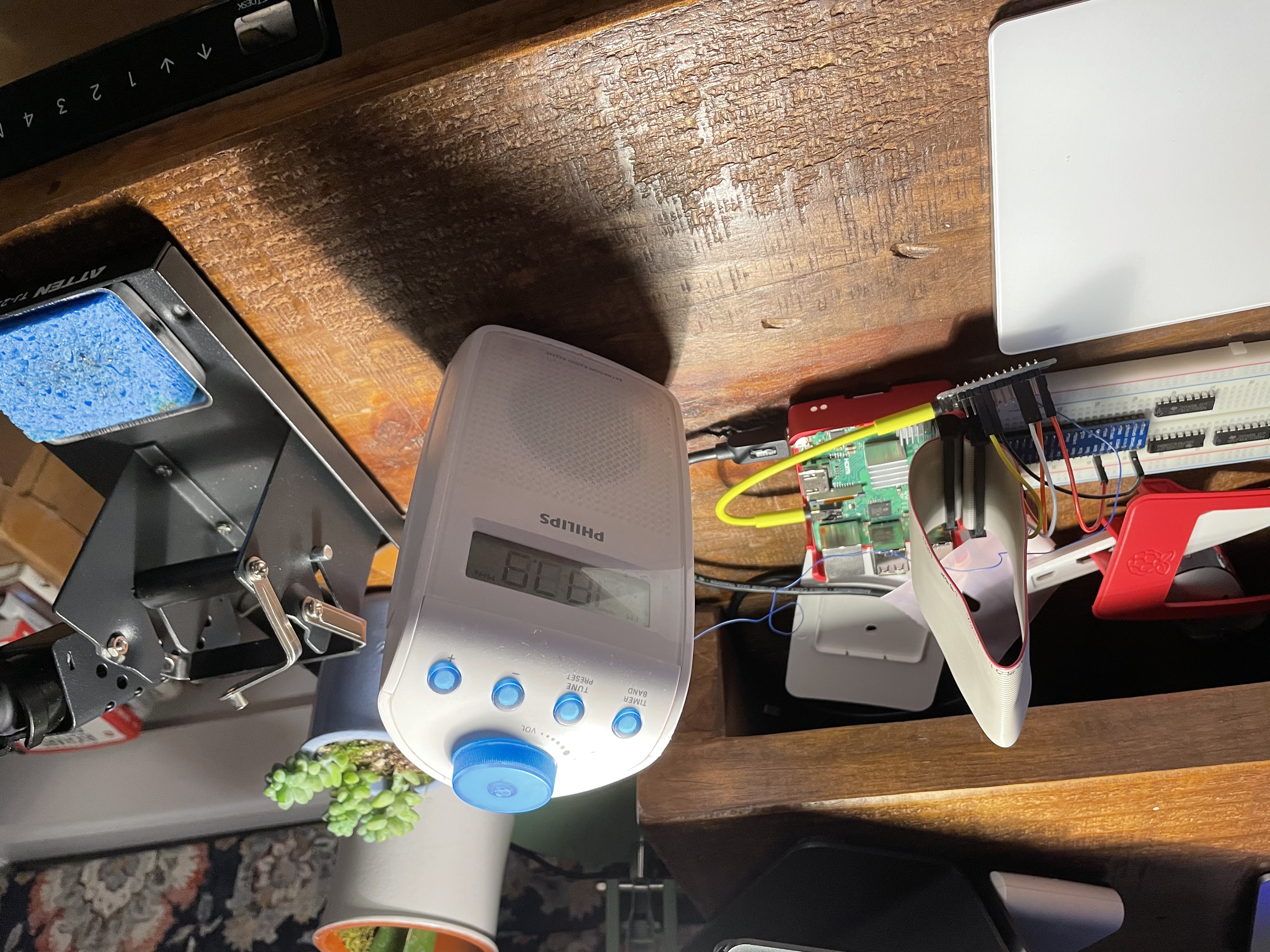
My test setup is all ready!
Software setup
The instructions here are pretty straightforward too, but as a general rule, I don’t love running things as root that don’t come directly from the distribution. I understand it’s a bit silly, especially since I will trust some of the pip3 things, but it’s a habit.
You can actually look into what their script is doing, and kind of do it “manually”
$ sudo apt-get install -y python3 git python3-pip
$ sudo update-alternatives --install /usr/bin/python python $(which python2) 1
$ sudo update-alternatives --install /usr/bin/python python $(which python3) 2
$ sudo update-alternatives --skip-auto --config python
$ sudo apt-get install -y i2c-tools libgpiod-dev
$ pip3 install --upgrade RPi.GPIO
$ pip3 install --upgrade adafruit-blinka
$ sudo raspi-config nonint do_i2c 0
$ sudo raspi-config nonint do_spi 0
$ sudo raspi-config nonint do_serial 0
$ sudo pip3 install adafruit-circuitpython-si4713
Missing line
Trying to follow the doc step by step, it seems that the test file is missing an import line.
The example on Adafruit’s site is missing an import. Nothing big, but in case you’re running into this.
import digitalioOnce that’s fixed, I can run a frequency scan, and I can confirm that some of the frequenies that I know carry a radio station (and there are MANY in New York) show a higher signal ratio. So far, so good.
The full example though had the missing import line, and everything seemed to be working.
Testing
For now I’m just going to use a jack-to-jack audio cable, and play an online radio. The --nodisp ffmpeg option comes in handy, when you just ssh into your Rasbperry.
I listen to “Radio Classique”, a French classical music station quite a bit. One neat thing is that from midnight to 6am, they don’t play ads, and that it 6p to 12a in New York, so that’s pretty cool for the evenings.
At the time of writing, this command line was working.
ffplay -nodisp -v verbose https://radioclassique.ice.infomaniak.ch/radioclassique-high.mp3Avoiding the jack cable
I was already thinking about the finished product, and I didn’t love the idea of a jack cable going out of the RPi box, and back inside to connect to the FM transmitter. There had to be a batter option!
Digital Input
As I was looking through the chipset datasheet and programming guide, it looks like there’s digital audio input. That would be a prety cool thing to use.
Let’s try it out! What would it take on the Raspberry side?
Digital Output
There are several input modes supported by the Si4713 chip , one of them I2S. I’m really not going to be in the business of looking at rising clock fronts, so either the RPI supports I2S, or I’m just sticking with my initial design with a jack or something else similar.
Following this article, I’m changing the /boot/config.txt file, rebooting, and as I’m ready to try, I come to a very simple question.
Where are the digital input pins?
And now, the disappointment: how do I plug it? Where are the pins?
Apparently they are not connected to a header. Maybe I’ll need to do some soldering?
Well, actually it’s even worse: looking at the schematics pins 13 and 14 which I need (check out the datasheet are set to the ground :-(
Well, that will teach me to not look for the full picture before starting to play with the software side.
So jack cable?
Thing is, I really want to avoid two things, in order of priority
- Soldering anything on the RPI board. I’ve done that in the past for a backup server project that I’ll be documenting later, and that was a mess.
- Having a jack cable out of the RPI. I’m hoping I can fit the FM transmitted in the RPI box, and having that cable going out and back in is pretty awful.
There may be a way: it’s technically possible to output analog audio out of the RPI header.
There are multiple articles about it, this is a pretty good one. Basically, you can get audio on header pins, but it’s going to be pretty garbage, because again it’s made from square signals.
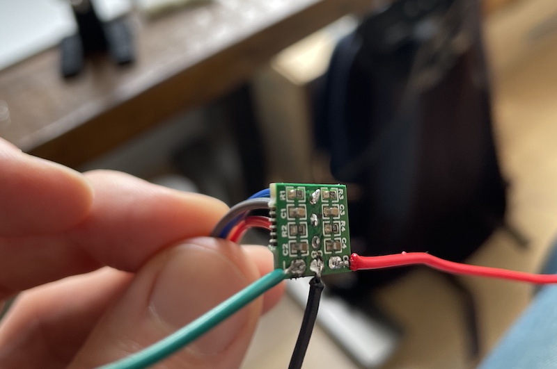
This is where this inexpensive PWM filter is going to be helpful. For less than $2 (at the time of writing, $1.95), it does exactly what I want.
More fun soldering
I’m terrible at soldering. Originally, all was well, but soon enough, the green wire came loose, and as I tried to resolder it, the whole pad got unstuck from the PCB.
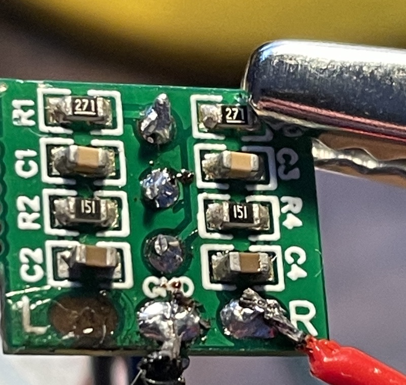
I ended up having to solder directly to a condensator. But it worked!
Where we are now, what’s next.
I have a working chain, and I just was to add a few things
- Detect when audio is coming, and turn power off otherwise
- Send some info (Podcast title, etc.) in the RDS messages
- Oh, and write the whole thing in Go, because I like Go.