
IR-controlled A/C (6/many) - The oscilloscope and other adventures
Time to gear up
My hunch at this point was that timing was off, or that most of the time, nothing was leaving the IR led. My dad happens to have an oscilloscope, so I was hoping I would be able to look at that.
Too bad, I thought I remembered it was a digital one, and that I would be able to actually “capture” the signal at the GPIO, but alas I remembered incorrectly. I was however going to use it to check at least that I could make the GPIO move as intended.
There were good news:
- When sending out the full sequence I could see something happening
- It seemed to happen for a fairly long time (several hundreds of milliseconds)
- I was also able to “manually” raise or lower the GPIO.
The reason I tested the last point is that I got into my head that maybe the circuit was introducing some kind of signal smoothing and tha the timing weren’t good anymore.\
So my plan was just to send a periodical signal to the GPIO, measure the timing,
and look if it was the same around the LED. I used pigpio for this (more on this
later) with a tiny bit of C.
First part went great: the GPIO was going up and down exactly as I
designed.
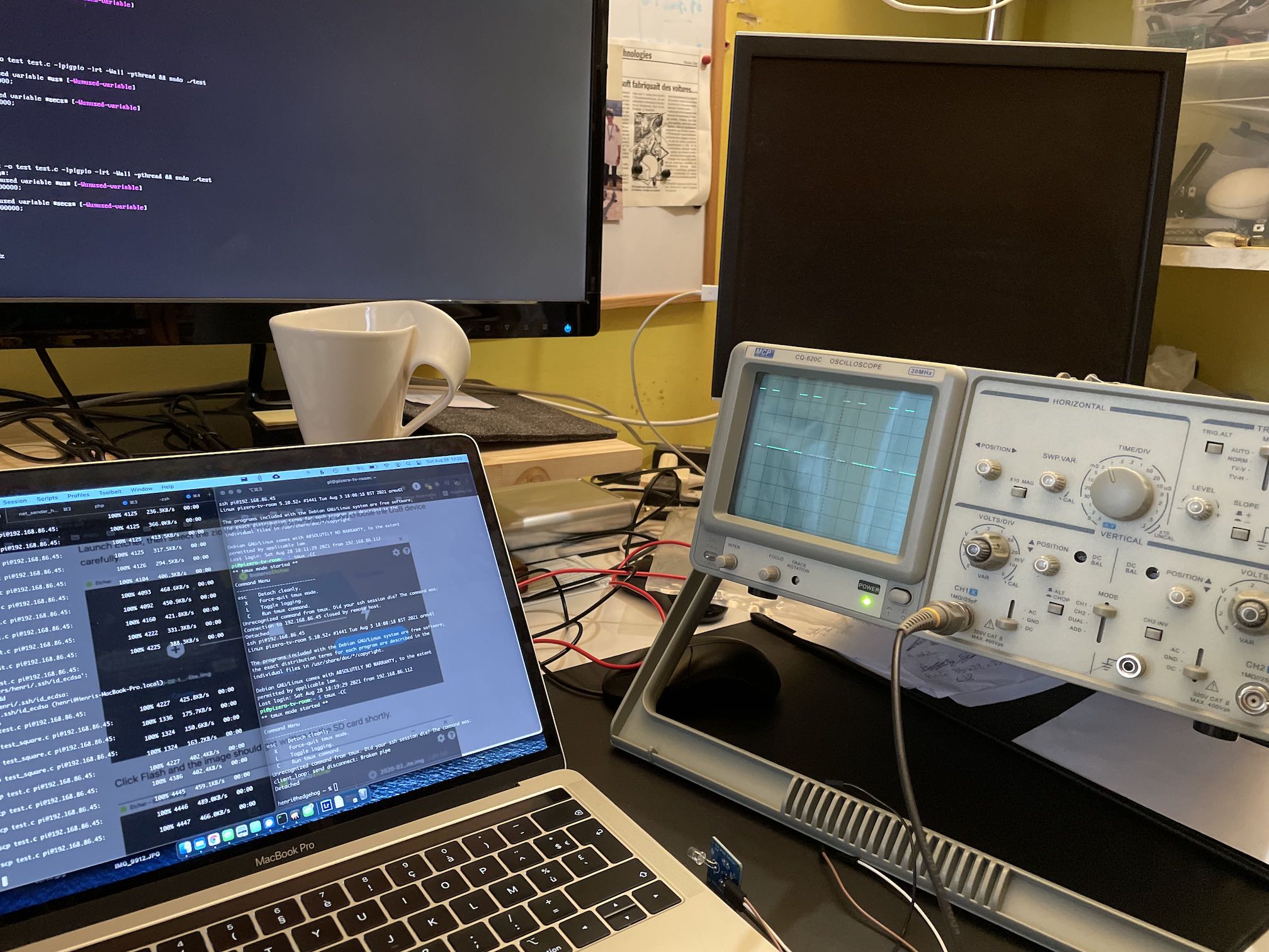
The second part brought something very unexpected: I found 3.3V aroud the LED
at all times. Now, I’m not great at electronics, and I had to ask my brother
for help.
The following diagram explains it all.
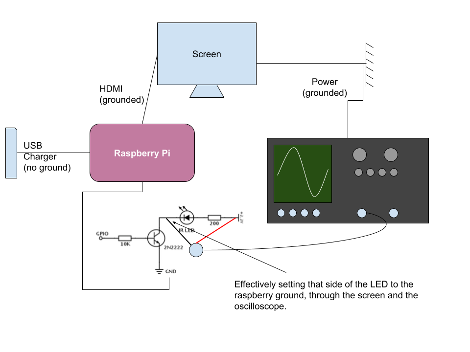
In a nutshell, while on its own the Rasperry Pi isn’t grounded, the HDMI cable to the screen grounds is. And through that, the ground of the oscilloscope’s probe put that side of the LED to the ground, while the other side is connected to solid 3.3V.
All in all it’s not that interesting, but it really felt like everything that could go wrong did go wrong.
Should have done that earlier.
Turns out, I could have done all of this as home: piscope is a GPIO library that will turn your Rasbperry Pi into a signal analizer, more of less.
My theory now was basically that the Pi ended up not being “real time” enough to
hold all the timings. Some part of the message would come late, depending on
interruptions going on, etc…
Now that I had a signal analyzer at hand, that was going to be way easier to
check.
So I captured a full signal (roughly 450 ms), and I modified the daikin.py
file of the daikin-pi package to add the timing of each byte, and the binary
content so that I could do some sanity checks.
This is an extract of such a command in the lircd.conf file
# long gap
430 35500
# Timer = 254.920
# frame header
3440 1720
# 11 da 27 00 00 39 26 00 af bf 00 06 60 00 00 c1 80 00 86
# Timer: 260.080 ms
# 10001000
430 1320
430 430
430 430
430 430
430 1320
430 430
430 430
430 430
# Timer: 268.740 ms
# 01011011
430 430
430 1320
430 430
430 1320
430 1320
430 430
430 1320
430 1320
# Timer: 280.070 ms
# 11100100
430 1320
430 1320
430 1320
430 430
As you can see, it makes it very easy to check the timing. I would just go to 254.920ms in the PiScope capture, and see that it coincides with the beginning of the frame header, etc.
And tadah! It so happens that it does not.
Apparently, I’m running into timing issues. It’s surprising because many people
have used lirc + GPIO on a Raspberry Pi to do exactly what I’m doing, but it
became pretty clear this was the issue. Maybe I was the only one with a
Rasbperry Pi Zero, which is quite slower than a Pi 3.
Next steps
I could get a few more USB IRToys, based on the assumption that the timing would be handled by the IrToy itself (the full sequence would be send over USB), but
- that’s a pretty wild assumption
- I’m kind of stubborn.
No, instead I decided I was going to drive the GPIO myself. Well, not quite, because there’s no chance I could be realtime enough either. But the pigpio library looked like I could set up a sequence, and the hardware would take care of it. Worth trying.